| |


Next: Universal User Interface and
Up: Control Board
Previous: Output Assign Module
Contents
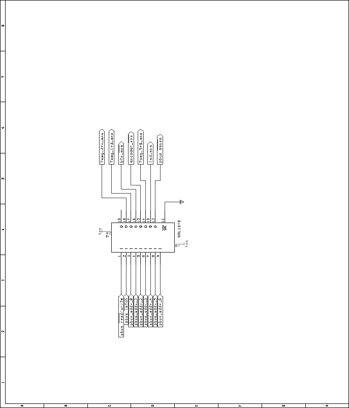
As in other DACS modules, a 16V8 GAL is used for Pbus address decoding
and enable signal generation. Figure 48 shows the pin
layouts for this GAL. The VHDL code used to
generate the GALs is included in the appendices, on page ![[*]](crossref.png) . .
Figure 48:
Transport control module, address decoding GAL schematic.
 |
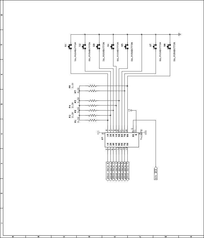
The transport control module contains 7 pushbuttons, the status of
which need to be detected by the microcontroller. The identical
latching and firmware debouncing scheme is used in this module as is
used in the output assign module. Figure 49 shows
this circuit.
Figure 49:
Transport control module, momentary pushbutton decoder schematic.
 |
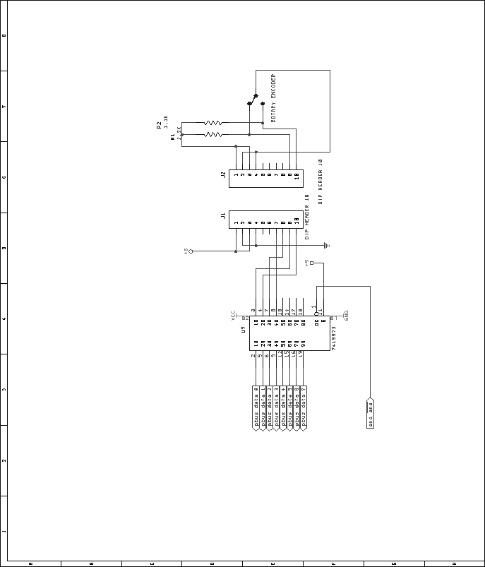
A rotary shaft encoder is used as a data entry wheel in the transport
control module. This encoder outputs two bits, which represent the
position of the shaft. Hardware quadrature decoders can be used to
give direction and clock signals. However, in the interest of
conserving board space, this decoding will take place in firmware. A
simple latching scheme is used to input the data from the encoder.
Figure 50 shows the circuit for the encoder. Note that
the rotary encoder present in the universal user interface section of
the control board also connects to this circuit.
Figure 50:
Transport control module, rotary encoder interface schematic. This
also acts as the interface for the encoder on the universal interface module.
 |
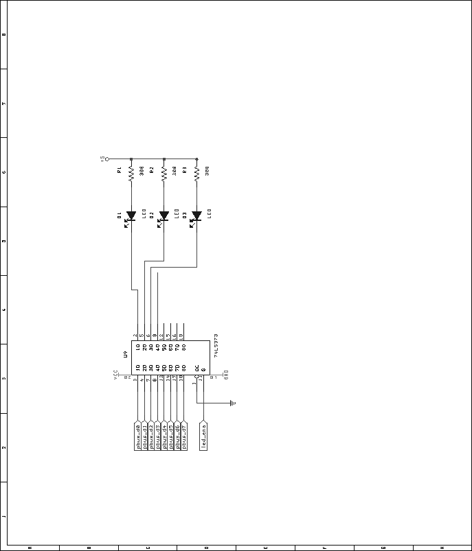
Three LEDs are present on the transport control module, to indicate
various statuses. A simple 74LS373 current-sinking setup is used to
drive these LEDs, as shown in figure 51.
Figure 51:
Transport control module, LED driver schematic.
 |
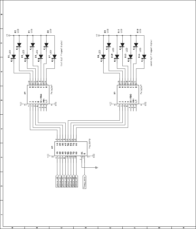
A pair of 7-segment displays are present in the transport control
module to display track information. These displays are connected in
a very similar fashion to those in the output assign module. Figure
52 shows the schematic.
Figure 52:
Transport control module, track select 7-segment display
decoder and driver schematic.
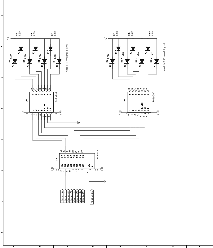 |
Another four 7-segment displays are used in this module to display a
time value. These displays are connected in a similar fashion to the
track indicator, with the exception that the ripple-blanking and
zero-blanking features are not used. Figure 53 shows
the schematic used. Two of these circuits are present in the module.
Figure 53:
Transport control module, time indicator 7-segment display
decoder and driver schematic.
 |
Next: Universal User Interface and
Up: Control Board
Previous: Output Assign Module
Contents
Steve Richardson
2000-07-06
|
Table of Contents
![[PDF]](/~prefect/images/pdficonsmall.gif) [Whole document in PDF 1.9MB]
[Whole document in PDF 1.9MB]
[more photos and information]
|