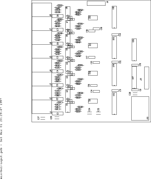
prefect
Home Engineering Publications
DACS: Audio Input Module
 
  next up previous contents
Next: Audio Mix Module Up: Mixer Unit Previous: Mixer Unit   Contents

Audio Input Module

Four audio input modules are used in the prototype mixer unit. Figure 80 shows the silkscreen/assembly layer for the audio input PC board. Table 5 shows the bill of materials for this board. Figures 81 and 82 show the top and bottom routing layers, respectively. It should be noted that, due to an oversight in design, the volume trim portion of this board is not functional. The DS1800 IC's are replaced with fixed resistor values in the prototype.

Figure 80: Audio input module PCB, silkscreen/assembly drawing.
\begin{figure}
\psfig{file=pcb/inp-silk.eps,width=5.5in,height=6.5in}
\end{figure}


Table 5: Audio input module, bill of materials.
REFDES QTY DESCRIPTION
R1 - R32,R34,R37,R40,R43,    
R46,R49,R52,R55 40 20K 1% metal film
R33,R35,R36,R38,R39,R41,R42,    
R44,R45,R57,R48,R50,R51,R53,    
R54,R56 16 10K 1% metal film
C1 - C8 8 0.47uF metallized polyester
C9 - C33 24 0.1uF monolithic
C34 - C38 5 10uF electrolytic
U1 - U12 12 NE5532
U13 - U16 1 DS1800 (not used, mis-design)
U17 1 GAL16V8
U18 1 74LS373
J1 - J8 8 Re'an 1/4 inch PCB mount switched jack
J9 1 16-pin DIP header
J10 1 Molex Mini-Fit Jr. 8-circuit right-angle
J11 1 20-pin DIP header


Figure 81: Audio input module PCB, component-side routing.
\begin{figure}
\psfig{file=pcb/inp-top.eps,width=5.5in,height=6.5in}
\end{figure}

Figure 82: Audio input module PCB, solder-side routing.
\begin{figure}
\psfig{file=pcb/inp-btm.eps,width=5.5in,height=6.5in}
\end{figure}


next up previous contents
Next: Audio Mix Module Up: Mixer Unit Previous: Mixer Unit   Contents
Steve Richardson 2000-07-06
Table of Contents

[PDF] [Whole document in PDF 1.9MB]

[more photos and information]

 
Page last modified:
Copyright © 1993-2000 prefect - All Rights Reserved.