
|

|
DACS: Audio Output Module | 
|
|
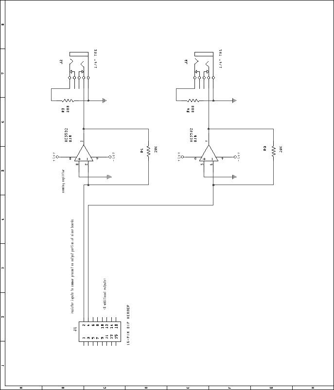
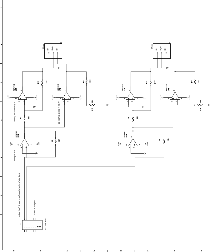
Next: Microcontroller Module (Pbus and Up: Mixer Unit Previous: Digital VU Module Contents Audio Output ModuleThe audio output module is fairly straightforward in that it has no digital section. Two varieties of output modules exist: balanced and unbalanced. The unbalanced output module uses 1/2 of an NE5532 dual op-amp as an output buffer/amplifier. This same op-amp also acts as the summing amplifier, to sum the signals from all of the mixer chips together. Figure 67 shows two channels of the unbalanced output stage in schematic form. The balanced output modules uses 1/2 of an NE5532 dual op-amp as a summing amplifier, to sum the signals from all of the mixer chips together. Two additional op-amps are used to generate buffered and inverted signals, to provide a balanced (differential) output. Figure 68 shows two channels of the balanced output circuit. NE5532 op-amps are rated to acceptably drive a 600 ohm load, thus conceivably making the system capable of driving 600 ohm terminated lines. However, research 1 suggests that ``the popular NE5532 dual IC, which is found in unbuffered form as a `transformerless' output amplifier in many low-cost designs, will show a significant drop in its maximum sustained output level when terminated. The same IC coupled to a pair of high-current output driver stages, while more expensive to manufacture, is a legitimate line power amplifier.'' This is something of a concern, but the specifications for this output module do not dictate that the unit be capable of driving 600 ohm lines, as the maximum output level is specified in dBu, not dBm. The beauty of the modular design of the DACS mixer shines through here, as an output module capable of more effectively driving 600 ohm loads could be designed and substituted for this module. For now, this is not a major concern, as the intended use is more for input into high-impedance devices such as amplifiers, equalizers, etc.Next: Microcontroller Module (Pbus and Up: Mixer Unit Previous: Digital VU Module Contents Steve Richardson 2000-07-06 |
Table of Contents
| |
![[PDF]](/~prefect/images/pdficonsmall.gif) [Whole document in PDF 1.9MB]
[Whole document in PDF 1.9MB]