
|

|
DACS: Bus Combiner and Switcher Module | 
|
|
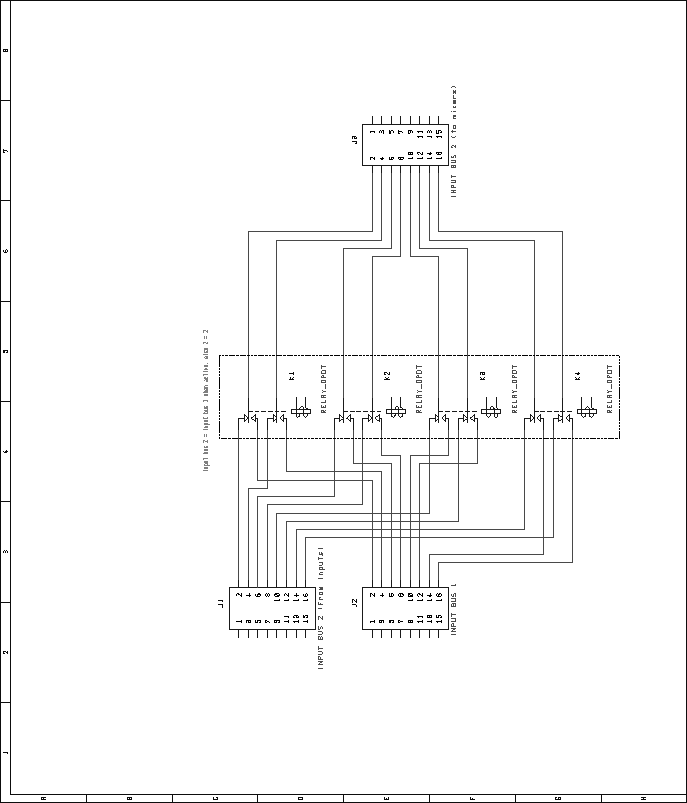
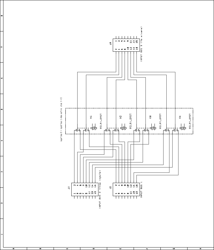
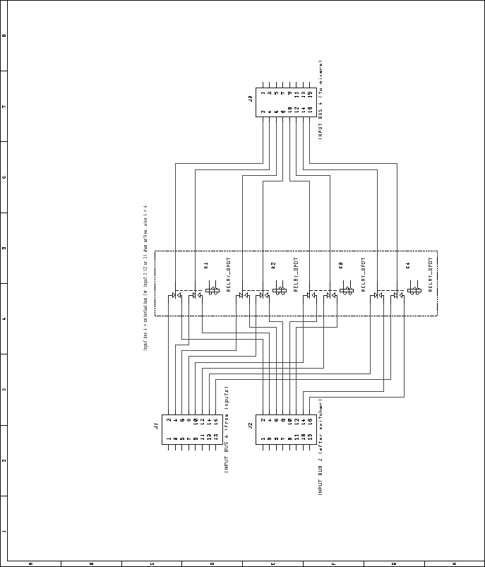
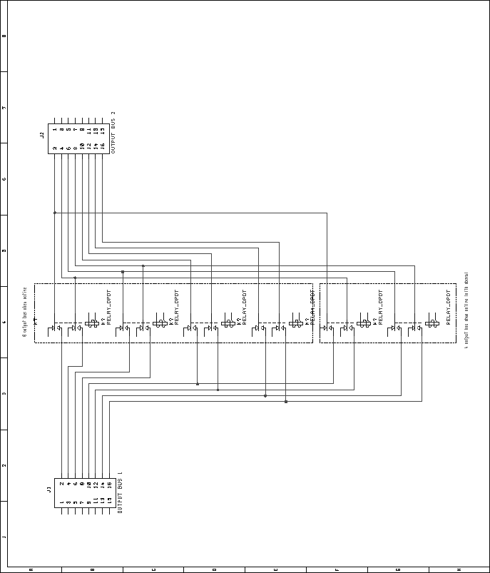
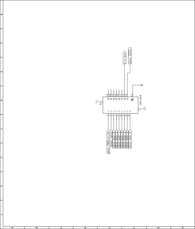
Next: Digital VU Module Up: Mixer Unit Previous: Audio Mix Module Contents Bus Combiner and Switcher ModuleRelays were chosen over an electronic switching scheme for reasons of cost and simplicity. Many types of audio-quality electronic switches exist, but most are rather expensive. Additionally, many have limitations such as operating voltage ranges, latch-up problems, etc. Relays are inexpensive, and do not have these limitations. However, relays consume a fair amount of current, and depending on the type, they may not switch silently. These limitations seem to outweigh the potential problems involved with electronic switches, however. To switch the source of the second input bus between the second group of inputs and the first group of inputs, four DPDT relays are used. The normally-closed portion of these relays connects the second bus to the second group of inputs by default. Figure 61 shows the schematic for the audio portion of this circuit. In a similar fashion, the source of the third input bus is switchable between input group one and input group three. Four DPDT relays are used for this switching, with the normally-closed portion defaulting the switcher to group three. Figure 62 shows the schematic for the audio portion of this circuit. Lastly, the source of the fourth input bus is switchable between input group four, and the input bus two. This allows the fourth input bus to be sourced from the fourth, second, or first input group. Figure 63 shows the schematic of the audio portion of the circuit. In addition to switching the input buses, the output buses can be combined, down to just four outputs. This is done in only two steps. Combining the first output bus with the second output bus reduces the number of outputs to from sixteen to eight. Further combining the top four with the bottom four lines reduces the number of outputs to four. As in the other portions of the bus switcher/combiner module, DPDT relays are used for switching. Four relays are used to combine the first and second output buses. The normally-closed sections of the relays aren't used, while the normally-open sections are used to connect the respective lines of each bus together. To connect the first four with the last four, a pair of DPDT relays are used in a similar fashion. Figure 64 shows the schematic for this circuit. As with other Pbus modules, a standard 16V8 GAL is used for address decoding. Figure 65 shows the pin assignments for the GAL. The VHDL code used to generate the GALs is included in the appendices, on page![[*]](crossref.png) .
To drive the relays, a series of NPN power transistors are used.
The transistors are driven by a 74LS373 latch. Diodes are present
across all relay coils, to prevent transistor damage due to the
inductive kick of the relays. Figure 66 shows the
schematic for this circuit. .
To drive the relays, a series of NPN power transistors are used.
The transistors are driven by a 74LS373 latch. Diodes are present
across all relay coils, to prevent transistor damage due to the
inductive kick of the relays. Figure 66 shows the
schematic for this circuit.
Next: Digital VU Module Up: Mixer Unit Previous: Audio Mix Module Contents Steve Richardson 2000-07-06 |
Table of Contents
| |

![[PDF]](/~prefect/images/pdficonsmall.gif) [Whole document in PDF 1.9MB]
[Whole document in PDF 1.9MB]