| |


Next: Digital Control Bus
Up: Mixer Unit
Previous: Power
Contents
Several audio signals need to be distributed among many modules in the
mixer unit. To accomplish this, a bus
architecture is used. Each bus carries eight audio signals on
standard ribbon cable. Connection to each PC board is made via
standard IDC sockets, and board-mounted headers.
The signals on each ribbon cable bus are arranged such that they are
separated by a signal ground. This helps to prevent crosstalk between
channels carried on the same bus. The ground signals are only
to be connected at the bus combiner module, eliminating ground loop
problems.
Figure 32 shows the pinouts for the audio input buses, of
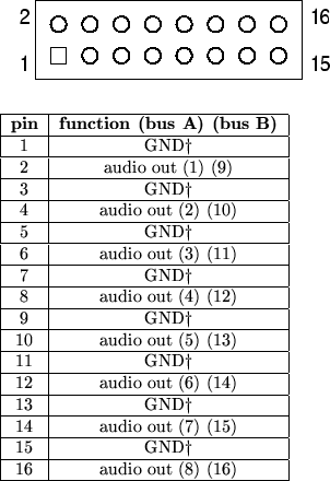
which there are four. Figure 33 shows the pinouts
for the two audio output buses. The signal levels on these buses
shall be no higher than +18dBu (about 6.15V peak).
Figure 32:
Audio input bus pinouts. The 32 audio inputs are carried on
four 16-pin headers.
 GND is only connected at the bus combiner board. GND is only connected at the bus combiner board.
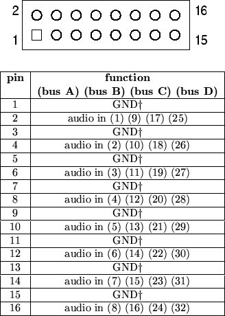 |
Figure 33:
Audio output bus pinouts. The 16 audio outputs are carried on
two 16-pin headers.
GND is only connected at the bus combiner board.
 |
Next: Digital Control Bus
Up: Mixer Unit
Previous: Power
Contents
Steve Richardson
2000-07-06
|
Table of Contents
![[PDF]](/~prefect/images/pdficonsmall.gif) [Whole document in PDF 1.9MB]
[Whole document in PDF 1.9MB]
[more photos and information]
|