
|

|
DACS: Bus Combiner Module | 
|
|
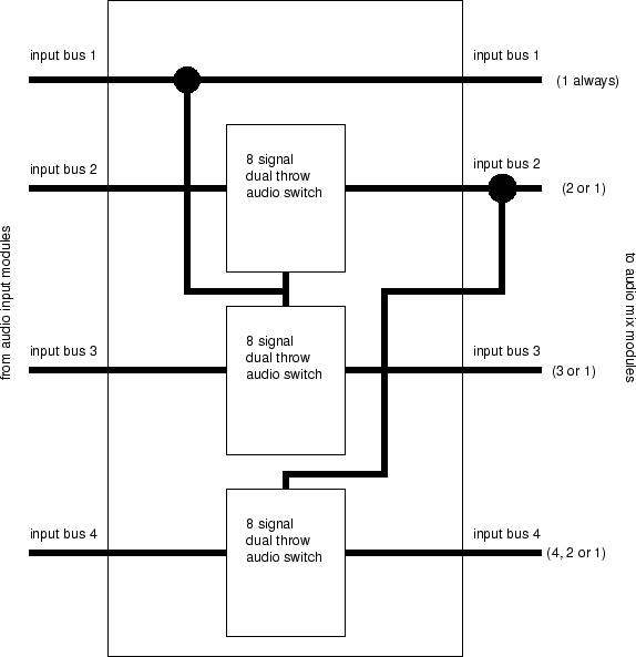
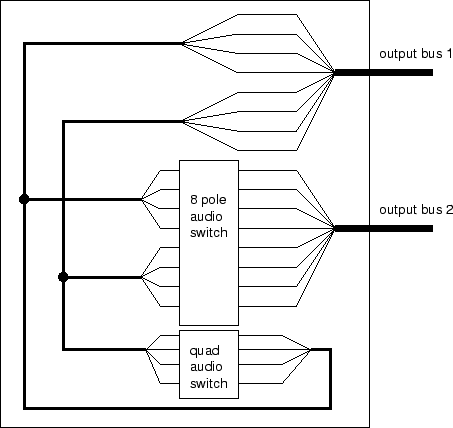
Next: Digital VU Module Up: Mixer Unit Previous: Audio Mix Modules Contents Bus Combiner ModuleThe bus combiner module provides the capability to dynamically reconfigure the signal architecture of the unit. Since the input and output sections are divided up in to buses of 8 audio signals, these buses can be combined or separated, changing the architecture of the mixer. This is only useful in systems with less than sixteen mix modules, as there are not enough mixer chips to fully cover a 32x16 mix configuration. In a four or eight mix module system, bus combination is necessary, to reduce the number of inputs to gain a large amount of outputs, or vice-versa. Figure 21 shows the input bus combiner diagram, while figure 22 shows the output bus combiner diagram. These are shown separately only for clarity; they shall be combined in the same module on the prototype.Next: Digital VU Module Up: Mixer Unit Previous: Audio Mix Modules Contents Steve Richardson 2000-07-06 |
Table of Contents
| |
![[PDF]](/~prefect/images/pdficonsmall.gif) [Whole document in PDF 1.9MB]
[Whole document in PDF 1.9MB]