
|

|
DACS: Overall Functional Design | 
|
|
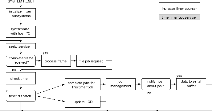
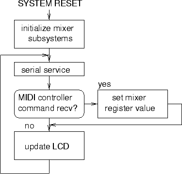
Next: Component Functional Design Up: Mixer Unit Previous: Design Overview Contents Overall Functional DesignFigure 98 depicts a functional flow diagram for the intelligent mode of operation for the mixer unit. At system reset, all internal subystems are initialized. System hardware is polled to determine what options are installed in the unit. At this time, the unit enters a host synchronization mode. During this time, the mixer unit attempts to establish communications with the host PC. Once communications have been established, the mixer unit informs the host PC of its configuration and enters the main program loop. The main loop begins with a serial device service routine. If a complete frame has been successfully received, this frame is processed. Assuming the data are valid, the job request from the host PC is entered into the job queue. Execution continues by checking the timer value. If the appropriate amount of time has passed, all pending mixer jobs for the current time slice are serviced. Maintenance of the job tables is then completed to remove completed jobs and updating time-to-live values in unfinished jobs. Should a job ending require notifying the host PC, the data are output to the serial buffer at this point. The status LCD is updated with current information periodically. This action is serviced by the timer dispatch. After timer processing, execution loops back to the top. This cycle repeats until the unit is powered off or reset. Should, at any time, either the host PC or the mixer unit become ``confused,'' the confused party shall re-enter synchronization mode. Both the firmware and the host PC software shall recognize, in normal operating mode, synchronization data coming from the opposite device. This shall cause that device to also enter synchronization mode, effectively resynchronizing both devices. To facilitate testing, and produce a functional demonstration, an extremely stripped down ``dumb'' mode of operation was implemented. Unfortunately, it is still the only functioning piece of firmware at the moment, due to time constraints. Figure 99 shows the functional flow for this mode of operation. Upon system reset, the underlying hardware is initialized. Immediately, the system enters a loop waiting for serial data. If a valid MIDI controller command is received, channel and value data from that command are used to immediately set mixer registers. The system then returns to waiting for another valid MIDI controller command. Periodically, the system LCD is updated with simple status information. This loop continues until the device is powered off.Next: Component Functional Design Up: Mixer Unit Previous: Design Overview Contents Steve Richardson 2000-07-06 |
Table of Contents
| |
![[PDF]](/~prefect/images/pdficonsmall.gif) [Whole document in PDF 1.9MB]
[Whole document in PDF 1.9MB]