| |
DACS Model 411 Modular Automated Audio Mixer
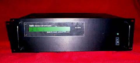 |
The 411, shown from the front. The 40x2 LCD, power switch, power LED, and
link LED are visible. The 411 is built into a 3RU X 19" rack-mount case.
|
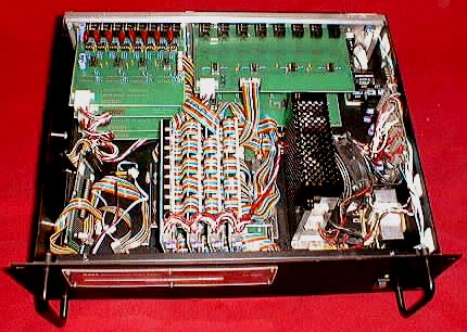 |
Inside of the Model 411. In the rear left, the four 8-input
balanced/unbalanced analog input boards can be seen. In the rear right, the
two analog output boards can be seen - the top is an 8-output
unbalanced 1/4" output, the bottom is an 8-output balanced XLR output. In
the center near the front are four mix engine cards. The architecture
supported up to 16 cards to obtain full 32x16 mixing capabilities. On the
left front, the pBus interface card can be seen. The 68HC11 microcontroller
board sat under the pBus interface card, but it had been removed prior to
this photo. Vertically mounted on the right side of the chassis is the
linear +/- 7VDC, +/- 14VDC, and +5VDC power supply. To the left of that
supply is an off-the-shelf +12V/+5V switching power supply, which had to be
added at the last minute because of the current draw of the bus combiner
module, which sits under the mix engine cards.
|
![[model 411 input board]](model_411_input_sm.jpg) |
8-input analog audio input board. Accepts balanced or unbalanced line-level
signals. Unstuffed parts were for input gain adjust circuit which had
design problems. NE5532 op-amps were used throughout the system.
There are four of these boards in the Model 411 mixer.
|
![[model 411 mix engine card]](model_411_mix_sm.jpg) |
32x1/16x2/8x4 mix engine card. Reconfigurable with bus combiner module.
The Analog Devices SSM2163 SPI-controlled 8x2 mixer ICs were the core of the
system. The logic at the top was the decode circuitry for the pBus
interface. The card was designed to support parallel SPI such that
independent, simultaneous communication with all four chips was possible.
The row of connectors on the bottom are for the audio bus connections which
are carried on ribbon cables with IDC connectors. There are four of these
boards in the prototype Model 411 mixer, but the architecture supports up to
16.
|
![[model 411 bus combiner board]](model_411_buscomb_sm.jpg) |
Audio bus combiner board. This board combined audio input and output buses
so that a DACS system with fewer than the maximum 16 mix engine cards could
be reconfigured. With all 16 mix engine cards, the system would always
function as a full 32x16 mixer. However, because it was cost prohibitive to
produce 16 mix engine cards (each mix engine card cost over $100) a
reconfigurable bus scheme was designed. This allowed the system to function
as a 32x4, 16x8, or 8x16 with 4 mix engine cards in the system.
|
![[model 411 unbalanced output board]](model_411_unbalout_sm.jpg) |
Unbalanced 8-output audio board. Provided eight tip-sleeve unbalanced
line-level outputs from the system.
|
![[model 411 balanced output board]](model_411_balout_sm.jpg) |
Balanced 8-output audio board. Provided eight XLR balanced audio outputs
from the system. It is worthwhile to note that both the balanced and
unbalanced PC boards are identical - it was designed to allow parts stuffing
to determine the configuration.
|
![[model 411 linear power supply]](model_411_power_sm.jpg) |
Hand-wired linear power supply. Provided +/- 7V for the mix engine cards,
+/- 14V for audio rails on the input and output boards, and +5V for digital
logic on the mix engine and input cards.
|
|
|


![[model 411 input board]](model_411_input.jpg)
![[model 411 mix engine card]](model_411_mix.jpg)
![[model 411 bus combiner board]](model_411_buscomb.jpg)
![[model 411 unbalanced output board]](model_411_unbalout.jpg)
![[model 411 balanced output board]](model_411_balout.jpg)
![[model 411 linear power supply]](model_411_power.jpg)